Introduction to Fluorescent Lighting Systems
Fluorescent lighting remains a cornerstone in commercial, industrial, and residential lighting solutions due to its energy efficiency and long lifespan. For lighting contractors, understanding the intricate details of fluorescent light diagrams is essential to ensure proper installation, maintenance, and troubleshooting. This handbook provides a comprehensive guide to the components, wiring, and operational principles behind fluorescent lighting systems, empowering contractors to deliver optimal lighting solutions.
Fluorescent lights operate on a fundamentally different principle than incandescent bulbs, relying on gas discharge and phosphor coatings to produce visible light. This difference necessitates a unique set of components and wiring configurations, which are best understood through detailed diagrams. By mastering these diagrams, contractors can avoid common pitfalls such as improper ballast selection, wiring errors, and compatibility issues.
In addition to their energy efficiency, fluorescent lighting systems are known for their versatility in various environments. They are available in a wide range of color temperatures, allowing contractors to tailor the lighting to the specific needs of a space, whether it be a warm, inviting atmosphere for a restaurant or a bright, clinical environment for a hospital. Furthermore, advancements in technology have led to the development of compact fluorescent lamps (CFLs) and linear fluorescent tubes, which can fit into a variety of fixtures, making them suitable for both new installations and retrofitting existing systems.
Moreover, understanding the environmental impact of fluorescent lighting is becoming increasingly important. While these systems are more energy-efficient than traditional incandescent bulbs, they do contain small amounts of mercury, which necessitates careful disposal and recycling practices. As a result, contractors must be well-versed in local regulations regarding fluorescent lamp disposal and the importance of educating clients about sustainable practices. By integrating this knowledge into their services, contractors can not only enhance their credibility but also contribute to a more sustainable future in lighting solutions.
Core Components of a Fluorescent Lighting System
The Fluorescent Tube
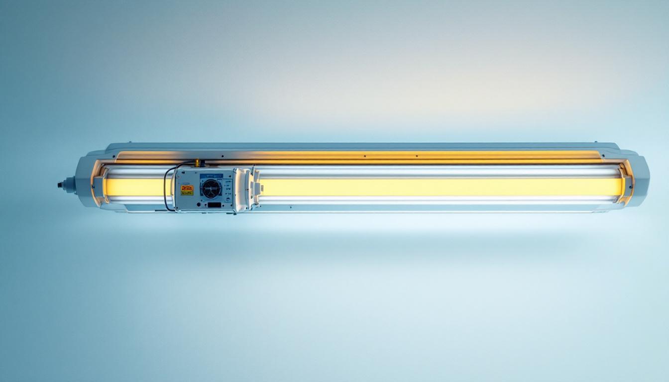
The fluorescent tube is the heart of the system. It consists of a sealed glass tube filled with low-pressure mercury vapor and inert gases. When an electric current passes through the tube, it excites the mercury vapor, producing ultraviolet light. This ultraviolet light then interacts with the phosphor coating on the inside of the tube, emitting visible light.
Fluorescent tubes come in various shapes and sizes, including T5, T8, and T12 diameters, each with different electrical and lighting characteristics. Selecting the correct tube type is crucial for system compatibility and efficiency. Additionally, fluorescent tubes are available in a range of color temperatures, from warm white to cool daylight, allowing users to choose the ambiance that best suits their environment. This versatility makes fluorescent lighting ideal for various applications, from residential spaces to commercial settings, where different lighting needs can be met.
The Ballast
The ballast is a critical component that regulates the current flowing through the fluorescent tube. Without a ballast, the tube would draw excessive current, potentially damaging itself or causing electrical hazards. There are two main types of ballasts: magnetic and electronic.
Magnetic ballasts are traditional and often heavier, utilizing inductive coils to limit current. Electronic ballasts, on the other hand, are lighter, more energy-efficient, and provide flicker-free operation. Understanding the ballast type and its wiring is essential for contractors to ensure system reliability and compliance with energy codes. Moreover, the choice of ballast can significantly affect the overall performance of the lighting system, including factors such as energy consumption and the lifespan of the fluorescent tubes. Some electronic ballasts also offer dimming capabilities, providing further flexibility in lighting design.
The Starter (for Preheat Systems)
In some fluorescent lighting systems, particularly older preheat types, a starter is used to initiate the lighting process. The starter provides a brief surge of current to heat the electrodes inside the tube, enabling the gas to ionize and produce light. Modern rapid-start and instant-start systems typically do not require starters, simplifying the wiring and improving efficiency.
While starters are less common in contemporary installations, understanding their function is still relevant, especially when dealing with retrofitting older systems. The starter’s role in preheat systems highlights the evolution of fluorescent technology, where advancements have led to improved reliability and reduced maintenance needs. Additionally, as energy efficiency becomes increasingly important, many users are opting for newer technologies that eliminate the need for starters altogether, further streamlining the fluorescent lighting system and enhancing its performance in various settings.
Understanding Fluorescent Light Wiring Diagrams
Basic Wiring Configuration
A typical fluorescent light wiring diagram includes the power source, ballast, tube, and sometimes a starter. The power source connects to the ballast, which then regulates current to the tube. The wiring diagram visually represents these connections, showing how the components interact to produce light.
For example, in a rapid-start system, the ballast supplies current to both the tube’s electrodes and the tube itself simultaneously, eliminating the need for a starter. The wiring diagram will show connections from the ballast to both ends of the tube, highlighting the dual function of the ballast.
Interpreting Symbols and Lines
Lighting diagrams use standardized symbols to represent components. For instance, a rectangle often denotes a ballast, while a circle with a filament inside represents the fluorescent tube. Lines indicate wiring paths, with solid lines typically representing live wires and dashed lines indicating neutral or ground connections.
Lighting contractors must be fluent in reading these symbols and lines to accurately interpret diagrams, especially when troubleshooting or retrofitting existing systems. Misreading a diagram can lead to improper wiring, posing safety risks and reducing system lifespan.
Common Wiring Configurations
Fluorescent lighting systems can be wired in several configurations depending on the tube type and ballast. The most common are:
- Preheat Wiring: Involves a starter and ballast wired in series with the tube electrodes.
- Rapid-Start Wiring: Ballast supplies current to electrodes and tube simultaneously, no starter required.
- Instant-Start Wiring: Ballast provides a high voltage to strike the arc instantly, with minimal electrode heating.
Each configuration has a distinct wiring diagram, and contractors must select the appropriate diagram based on the system specifications.
Troubleshooting Using Fluorescent Light Diagrams
Identifying Common Faults
Fluorescent lighting systems can experience several common issues, such as flickering, failure to start, or dim light output. Using wiring diagrams, contractors can systematically diagnose these problems by verifying wiring continuity, ballast function, and tube condition.
For instance, flickering often results from a failing ballast or loose wiring connections. By referencing the wiring diagram, contractors can trace the circuit to identify and correct these faults efficiently.
Testing Ballasts and Starters
Ballasts and starters are frequent points of failure. Using a wiring diagram, contractors can isolate these components and perform electrical tests such as continuity checks, resistance measurements, and voltage tests. Proper identification of ballast terminals and starter connections on the diagram ensures accurate testing and replacement.
Safety Considerations
Working with fluorescent lighting involves exposure to electrical currents and fragile glass tubes containing mercury vapor. Wiring diagrams help contractors understand the safe sequence of disconnecting and reconnecting components. Additionally, diagrams assist in verifying that grounding and neutral connections meet electrical codes, minimizing shock hazards.
Advanced Topics: Integration and Modernization
Retrofitting with LED Tubes
Many lighting contractors are now involved in retrofitting fluorescent fixtures with LED tubes to improve energy efficiency and reduce maintenance. Understanding the original fluorescent light diagram is essential to safely remove or bypass ballasts and starters, as LED tubes often require direct wiring to the power source.
Contractors must carefully follow manufacturer instructions and wiring diagrams to avoid damage to the LED tubes or electrical hazards. In some cases, the ballast is removed entirely; in others, it remains in place if compatible with the LED tube.
Smart Lighting Controls
Modern fluorescent lighting systems can be integrated with smart controls such as occupancy sensors, dimmers, and daylight harvesting systems. Wiring diagrams expand to include these control devices, showing how they interface with ballasts and power sources.
Lighting contractors must be adept at reading these enhanced diagrams to install and configure smart controls correctly, ensuring seamless operation and energy savings.
Best Practices for Lighting Contractors
Accurate Documentation
Maintaining accurate and up-to-date wiring diagrams for each project is vital. Contractors should document any modifications or retrofits to ensure future maintenance and troubleshooting are efficient. Digital tools and software can assist in creating clear, professional diagrams that comply with industry standards.
Continuous Education
The lighting industry evolves rapidly with new technologies and regulations. Contractors should engage in ongoing training to stay current with fluorescent lighting advancements and diagram interpretation techniques. This commitment enhances service quality and client satisfaction.
Compliance with Electrical Codes
Adherence to local and national electrical codes is non-negotiable. Wiring diagrams must reflect code-compliant installations, including proper grounding, wire sizing, and component ratings. Contractors should consult the latest codes and standards to ensure safe and legal installations.
Conclusion
Fluorescent light diagrams are indispensable tools for lighting contractors, providing a detailed roadmap for installation, troubleshooting, and modernization. By mastering the components, wiring configurations, and interpretation of these diagrams, contractors can enhance their technical expertise and deliver superior lighting solutions.
Whether working on new installations or retrofitting existing systems, a thorough understanding of fluorescent light diagrams ensures safety, efficiency, and client satisfaction. This handbook serves as a foundational resource to support lighting contractors in navigating the complexities of fluorescent lighting systems with confidence and professionalism.
Illuminate Your Projects with LumenWholesale
Ready to take your lighting installations to the next level? At LumenWholesale, we provide lighting contractors with exceptional, spec-grade fluorescent lighting products at unbeatable wholesale prices. Say goodbye to local distributor markups and hello to our extensive selection that meets the highest industry standards. With free shipping on bulk orders, you can trust that you’re getting premium quality without any hidden fees. Elevate your lighting game with the perfect blend of quality, affordability, and convenience. Visit LumenWholesale today for Wholesale Lighting at the Best Value and light up your projects with confidence.